

Data-Path:
Data-Path is all about the flow of data from instruction memory to registers, ALU, Data memory, Program counter and the other components of hardware where appropriate data needs to go. Consider our 16 bit processor. We have a 16 bit ISA. The ISA says, the length of our every instructions will be 16 bit. And also says that we will have 3 type of instructions.
- R-type
| Opcode | rs | rt | Rd |
| 4 bit | 4 bit | 4 bit | 4 bit |
- I-type
| Opcode | rs | rt | Immediate |
| 4 bit | 4 bit | 4 bit | 4 bit |
- J-type
| Opcode | Target Address |
| 4 bit | 12 bit |
R-Type Data Path:
Instructions will be 16 bit. Bit 12:15 will be Opcode, 8:11 will be rs (source register 1 for ALU). Our ALU will get its 1st input from rs. Bit 4:7 will be rt (Source register 2 for ALU). rt is the 2nd input for ALU. ALU does operation with these two input data. We will see it later. Bit 0:3 will be rd. rd is the destination register. After doing operations ALU generates a valid result. We need to store this result. rd is the register address in Register file where the results will be stored. Now things will be clear when we will see a demonstration of R-type instruction’s data flow. We will pick randomly one R-Type instruction. For example we have picked addition operation. Suppose we will do:
add $s1 $t0 $s2
Arrange this instruction according to our ISA R-Type. This instruction says, add the value of $to and $s2. Then store the result in $s1. So here, rs = $t0, rt = $s2 and rd = $s1. According to our ISA, instruction should look like:
| Opcode (4 bit) | rs (4 bit) | rt (4 bit) | Rd (4 bit) |
| add | $t0 | $s2 | $s1 |
We have already decided what would be opcode for add, what would be the register number for $to, $s2, $s1 in our ISA.
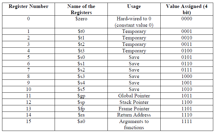
From these tables, write down the value of each field and convert into binary form.
| Opcode (4 bit) 12:15 | rs (4 bit) 8:11 | rt (4 bit) 4:7 | Rd (4 bit) 0:3 |
| add | $t0 | $s2 | $s1 |
| 0000 | 0001 | 0111 | 0110 |
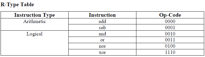
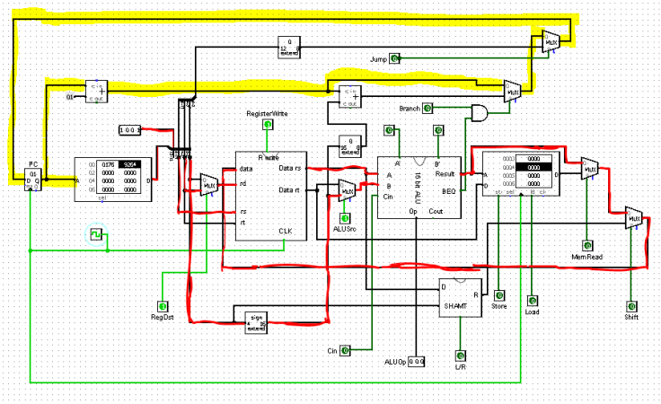
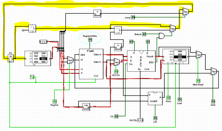
So, the instruction to be loaded in Instruction memory is “0000000101110110” for addition operation. For experimenting in logisim, we need to load the hex form of this instruction, which is “0176”. Let’s see, how the data is flowing –
Look at the picture above. We have loaded the instruction 0176 to instruction memory. So as we said, output of IM giving us the binary form of 0176.
Bit 12:15 is opcode. Which is 0000. It will go to the input of Control unit later. Bit 8:11 is rs. So, we have connected bit 8:11 to rs pin of register file. What it is doing is, taking the value of register rs ($t0 / 0001) and the value is coming out through “Data rs” pin as Input of ALU (pin A of ALU). Bit 4:7 is rt. rt is the register no of $s2. rt goes to the input of “rt pin” and it takes the value of $s2 register from register file. The value comes out through “Data rt” pin into a mux. Now this value supposed to go as 2nd input (ALU B pin). To do so, make mux select bit (ALUSrc = 0). Now ALU has got its two input. ALUOp = 000 does addition operation. Result of addition goes out through “result pin”. Our next task is to store this result in register $s1. Bit 0:3 is the address of $s1/rd. So connect bit 0:3 into rd pin of register file. It will select the desired register in register file. Now the last piece of puzzle is to bringing the result for “data” pin from ALU. So, the result coming out from the result pin goes into a mux. Make the mux select bit MemRead = 0 and then the result goes into another mux. Make shift = 0. Now result goes into “Data” pin of register file. rd is already selected. When the clock pulse is clicked, the result of $t0+$s2 will be stored in $s1. All R-type operations in our table will follow the same data path. Just need to change ALU operation when needed. After finishing execution of this instruction, PC should go for next instruction. So, pc will be PC+1 in our case. Yellow portion in the picture describes how the pc goes to the next instruction. We have to make Branch = 0 for that.
I-Type Data Path:
First of all, pick a random instruction from I-type instruction. Suppose we want to do:
addi $s1 $t1 4
What this instruction will do is, Send the value stored in register $t1 to ALU as ALU input A, Send 4 as ALU input B. Then add those and store the result in $s1 register. Like previous one, arrange the instruction according to I-type instruction model.
| Opcode (4 bit) 12:15 | rs (4 bit) 8:11 | rt (4 bit) 4:7 | Immediate (4 bit) 0:3 |
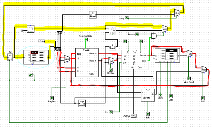
| addi | $t1 | $s1 | 0100 |
| 1001 | 0010 | 0110 | 0100 |
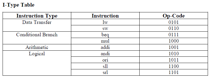
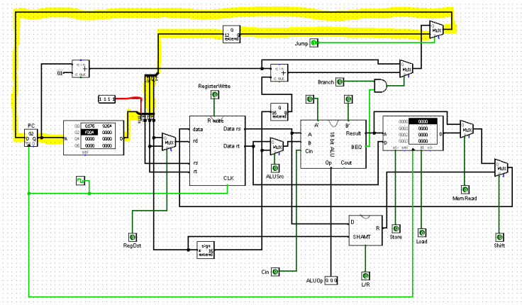
The binary form and hex form of this instruction is 1001001001100100 & 9164. Let’s see how it works-
Bit 12:15 goes to Opcode. Next 4 bit is rs. rs goes to rs pin. Like before, it sends the data stored in rs ($t1) to ALU input A through “Data rs” pin. We want to add 4 with $t1. $t1 is already in ALU. The last 4 bit (0:3) represents the immediate value 4. So, last four bit goes to a bit extender, because our ALU can do operation only with 16 bit data. The immediate value becomes 16 bit from 4 bit and goes to ALU input B. We must make ALUSrc = 1 to send immediate value to ALU input B. Now ALU does the add operation and output comes out though Result pin. Like before, make MemRead = 0 & shift = 0 to send the result to Register file’s data pin. So, result reached to data pin. Bit 4:7 decides which register will store the result. Though 4:7 bit is rt. But for immediate type operations, rt becomes rd. Bit 4:7 goes to rd. For that we select RegDst = 1. If clock pulse is clicked the operation addi $s1 $t1 4 will executed. PC will also become pc+1 like R-Type (yellow portion).
Jump:

The task of unconditional jump is, Jump to a specific memory address in instruction memory from current address.
Suppose we want to execute – J 4. This instruction will jump from current address to memory address 4.
| Opcode (4 bit) 12:15 | Target Address (12 bit) 0:11 |
| J | 4 |
| 1111 | 000000000100 |
Binary form and Hex form are 1111000000000100 & F004. Load that in instruction memory.
First 4 bit goes to opcode. Last 12 bit is the target address. Which means, next the value of program counter will be the target address or the last 12 bit. So the last 12 bit (0:11) goes to a mux. By selecting Jump = 1, mux sends the data to PC. When the clock pulse will occur, PC will be 4 instead of PC+1. It will automatically jump the instruction memory address from current to 0100. It is important to make RegWrite = 0, Store = 0, Load = 0 so that no data will be hampered stored in register file and Data memory.
Branch:
This circuit can execute only Branch Equal instructions. If two data are equal, then the BEQ output from ALU will give us 1 value.
Consider beq $t0 $t2 1
It says, if the values in register $t0 & $t2 are same, make PC = PC+1+1. Instead of PC = PC+1, if there was 2, then pc would become PC+1+2.
Re-arrange the instruction according to our ISA describes. beq is an I-Type instruction.
| Opcode (4 bit) | rs (4 bit) | rt (4 bit) | Immediate (4 bit) |
| 0111 | $t2 | $t0 | 1 |
| 0111 | 0011 | 0001 | 0001 |
Binary and hex form are 0111001100010001 & 7131.
Let’s see the data path:
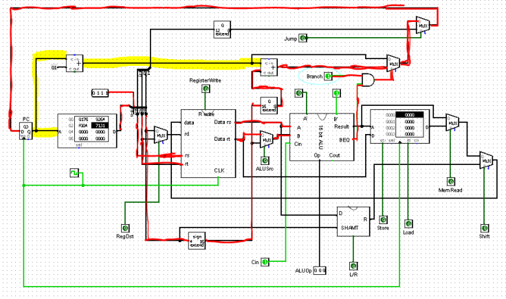
1st 4 bit goes to Opcode as usual. Next 4 bit is rs which goes to rs pin of register file and sends data to ALU A pin. And then next 4 bit is rt which goes to rt and sends data to ALU B pin (Make ALUSrc=0). ALU does minus operation with those value. If input A and B are equal (A-B=0), then BEQ output of ALU will be 1. We made Branch=1. So, if BEQ gives us 1 and branch is also 1 then AND gate will produce 1 which is the select bit of the mux. Now last 4 bit is the Level or immediate value. It goes to an adder where another input of that adder is PC+1. This adder makes PC=PC+1+1. If the AND gate generates 1, then this PC+1+1 will be sent as next pc. (Of course make jump=0)
With above examples, we have understood how the data flow works and how to convert mips to any type of binary/hex form. From now, I will show only the data-path flow without any explanation.
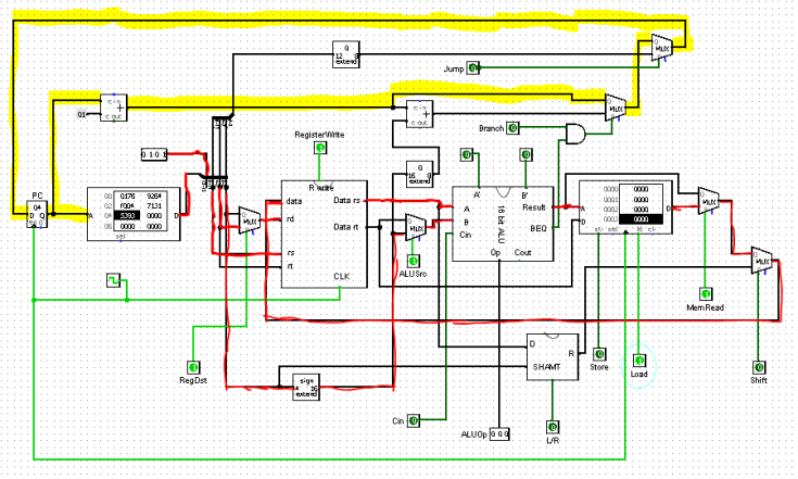
Load Word:
Instruction: lw $s4 3($t2)
Instruction type: I-Type
| Opcode | rs | rt | immediate |
| lw | $t2 | $s4 | 3 |
| 0101 | 0011 | 1001 | 0011 |
Hex form: 5393
Data-Path:
Store Word:
Instruction: sw $s0 2($s1)
Instruction type: I-Type
| Opcode | rs | rt | immediate |
| sw | $s1 | $s0 | 2 |
| 0110 | 0110 | 0101 | 0010 |
Hex form: 6652
Data-Path:

1 Pingback